In the first article “The basics of direct acting gas pressure regulators” we ended with the introduction of the compensation diaphragm. We will continue from there. If you haven’t read the first article it might be best to start there or, if you have read it, do a quick refresher. You can find the blog here: https://www.dgfg.eu/the-basics-of-the-direct-acting-gas-pressure-regulator/
The Compensating Diaphragm
The compensating diaphragm has two functions:
- It must be able to resist the differential pressure between pe/pu (inlet pressure) and pa/pd (outlet pressure)
- It must not obstruct the stroke movement of the valve plate.
To make this possible the diaphragm is made from two layers: On the low pressure side it consists of a fabric layer, on the high pressure side it consists of a rubber layer.
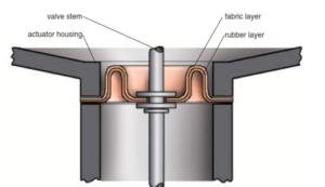
Risk of pressure applied from the wrong side
If pressure is applied from the wrong side, for whatever reason the pressure on the outlet becomes higher than on the inlet (typically when pressure testing the pipeline) the diaphragm will flip over. A pressure differential as little as 0.5 bar is enough to get the gas through the fabric and push the rubber of the fabric. Without the support of the fabric the rubber will burst and lose it’s function. So always apply and relief pressure on the correct side.
The correct way to start:
Build up the pressure (through the inlet ball valve), compartment for compartment until the outlet side is pressurized up or above the setpoint. Only then should the outlet valve be opened.
The correct way to stop:
Reduce pressure, close the outlet valve, (close the inlet valve), start venting starting at the outlet side by use of vent valves.
Setpoint spring in gas pressure regulators
The typically falling characteristic curve of a gas pressure regulator with a spring/diaphragm system is caused by the setpoint spring used. The force of a spring changes when it is being compressed. The more a sprig is being compressed, the greater the return force. Looking at the full and partial load range, the direct correlation to the change in length of the pretensioned setpoint spring can be seen:
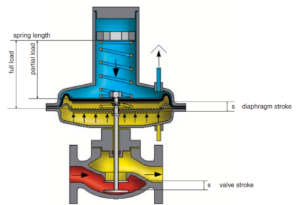
The setpoint spring is compressed by the length of the valve stroke. This increases the spring force when the valve opening is smaller than fully open. Because each position represents a balance between the outlet pressure and the spring force, the outlet pressure must increase by a given value, to hold the measuring diaphragm in the corresponding position. This correlation can be expressed in the Following equations:
Force and pressure calculations
The spring force is calculated as: FF = c x L
(c = spring rating N/mm, L = compressed differential length)
The pressure force on the measuring diaphragm is calculated as: FD = pa x AM
(pa/pd outlet pressure, AM = area of compensating diaphragm)
For a stable regulating position applies: FF = FD
The difference between 2 points is represented by the following:
Differential pressure: pa1 – pa2
Stroke (s) = difference in spring length: L1 – L2
When inserted in the formula c x L = pa x AM this becomes c x s = pa1 – pa2 * AM
Rewritten to the difference in pressure between 2 operating points (pa1 – pa2) this becomes c * s / AM
This means that the difference in pressure depends on the valve stroke (s) and the constant factor c / AM.
When you use a spring of 100 mm with a stroke of 100 mm each difference in the stroke of 1 mm is a difference in length of the spring is 100/100 (1%). When you use a spring of 200 mm with the same stroke the relative change in length of the spring is 100/200 (0.5%). This means that the change in force of the longer spring compared to the smaller spring is less.
The bigger the measuring diaphragm is the more sensitive it is, this means less pressure is required to generate the same force.
The above tells us that when the spring and diaphragm are bigger there is less difference required in pressure difference between 2 operating points.
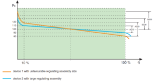
If we look at the 10% stroke (flow) and the 100% stroke (flow) it is obvious that at 10% device 1 requires 120% pressure and device 2 110% pressure. At 100% the same applies but 80 & 90%.
What this says is that how bigger the actuator (diaphragm) compared to the valve seat & stroke, the closer the 10 and 100% are to the desired setpoint 100% pressure.
This means it will be more accurate (AC). The smaller the AC number the better the accuracy. 10 stands for 1%, etc.
Want to know more about our products?
Please contact one of our product specialists on the website. The next article will be about the pilot operated regulators!